
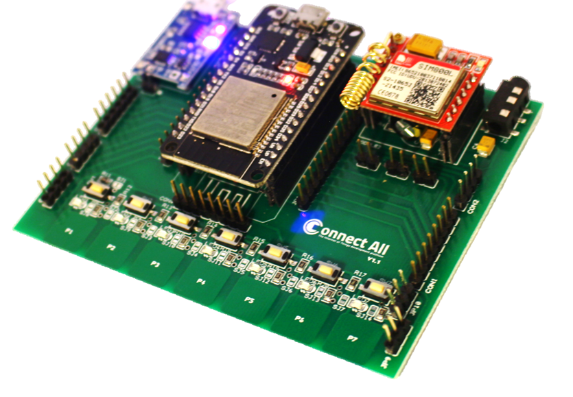
ConnectAll is a breakout platform based on the dev board ESP32 that is meant to breakout meanings of wireless data transfer and connect all of them together with a variety of devices and apps that can be connected over a local WIFI network, or via Bluetooth or even to communicate with GSM and GPRS on one educational platform using minimum power consumption.
Specifications & Features
This platform is considered a breakout modular development kit which supports plug & play connectivity with multiple operating modes that enables the developer to select between the desired functions.
Power
- Operating Voltage 5 VDC.
- Max load current 1500mA.
- Battery power ratings 3.7VDC 1500mA minimum.
- Battery charging up to 3.7Vdc/2000mA.
- Overcurrent protection threshold 3A.
- Constant Charge Current 1A
Connectivity & Abilities
- USB micro type cable supported
- WIFI protocol 802.11 b/g/n (802.11n up to 150 Mbps)
- WIFI frequency range 2.4 GHz ~ 2.5 GHz
- Bluetooth protocol Bluetooth v4.2 BR/EDR and BLE specification
- Bluetooth radio Rx NZIF with –97 dBm sensitivity
- Bluetooth radio Tx Class-1, class-2 and class-3 transmitter
- Bluetooth Audio CVSD and SBC
- Full modem serial port.
- Two microphone inputs and speaker output.
- SIM card interface.
- Quad frequency band: GSM 850, EGSM 900, DCS 1800, PCS 1900.
- GPRS multi-slot class 12(default).
- GPRS data downlink transfer: max. 85.6 kbps.
- GPRS data uplink transfer: max. 85.6 kbps.
- Support Packet Broadcast Control Channel (PBCCH).
- GPRS CSD transmission rates:2.4,4.8,9.6,14.4 kbps.
- External antenna pad.
- Support real time clock RTC.
Specifications
- 1 3.5mm speaker plug.
- 1 USB micro type power slot.
- 7 Onboard touch buttons.
- 7 customizable PU/PD pushbuttons.
- 7 Indication input LEDs.
- 3.7Vdc LiPo Charging.
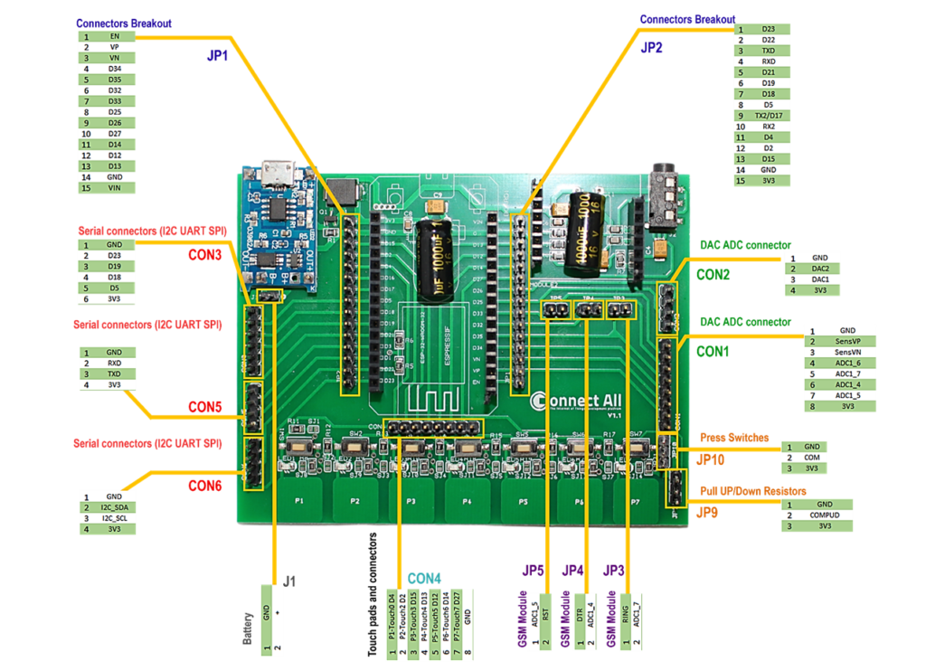
Pin Configuration
ConnectAll V1.1 usage illustration:
Mode A: Using the Kit as ESP32 Dev module shield using only JP2 & JP1, and then you can connect whatever you want using the ESP32 pinout configuration.
Mode B: Using the Breakout kit with its built-in components such as, LEDs, touch sensors, push button and the GSM module and you can follow the kit instructions to connect the board and start working with it.
In case of using the breakout kit as we will follow in the next sessions within the course, let’s go on illustrating the I/O pins of the kit:
- JP1 & JP2: These two header pins are used to connect the ESP32 pins.
- JP3, JP4, and JP5: these pins are used to connect the GSM module with the ADC (Analog to Digital Converter) pins channel 1 through the ESP32 and must be connected to with bridge if the GSM needed.
- JP9 & JP10: these pins used to connect the Pushbuttons to the ESP32 GPIOs pins, in our case we will connect JP10 between 1 and 2 (COM & GND), and for JP9 connect 2 and 3 (COM&3V3) using bridge connector, and then we can test the behavior of the Pushbuttons by pushing any button we will observe the lighting on of the connected LED this the Pushed button.