
SIM800L GSM/GPRS pinout
The SIM800L GSM/GPRS module has 12 pins which are NET, VCC, RST, RXD, TXD, GND, SPK-, SPK+, MIC-, MIC+, DTR, RING.
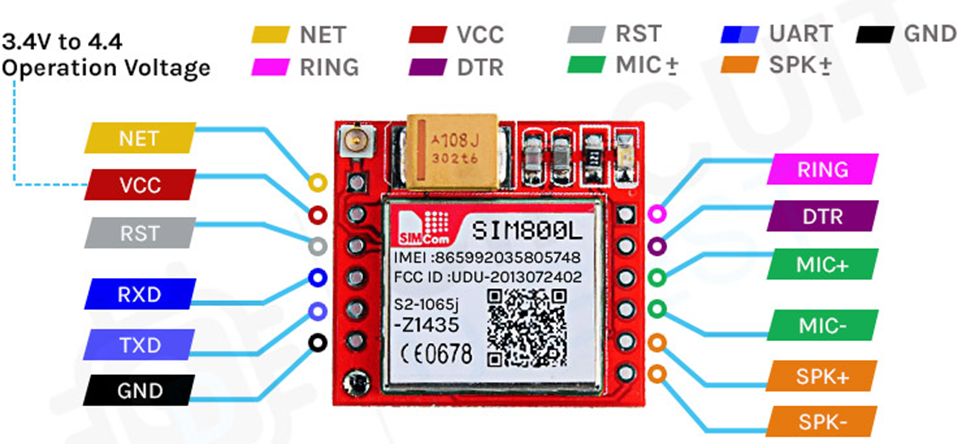
NET is a pin where you can solder the helical antenna that comes with the module.
VCC is the Power supply pin of the module, and it needs to be powered anywhere from 3.4V to 4.4 volts. Connecting this module to a 5V supply will most likely destroy it and if you connect it to 3.3V it won’t even run. A lithium battery or a buck converter with 2A current capacity is recommended for this module.
RST is the hard reset pin of the sim800L module. If you are having trouble communicating with this, pull the pin low for 100ms.
RXD is the RX pin for the module used in serial communication.
TXD is the TX pin for this module used in Serial communication.
GND is the Ground pin for this module; connect this pin to the Ground pin of the ESP32.
RING is the ring indicator pin of the module. This pin generally is active high. It will go low for 120ms to indicate incoming calls and can also be configured to pulse when an SMS is received.
DTR this pin can be used to put the module in sleep mode. Pulling the pin high puts the module in sleep mode and disables the serial. Pulling it low will wake the module up.
MIC+- These two pins can be used to connect an external microphone to the module.
SPK+- these two pins can be used to connect an external speaker to the module.
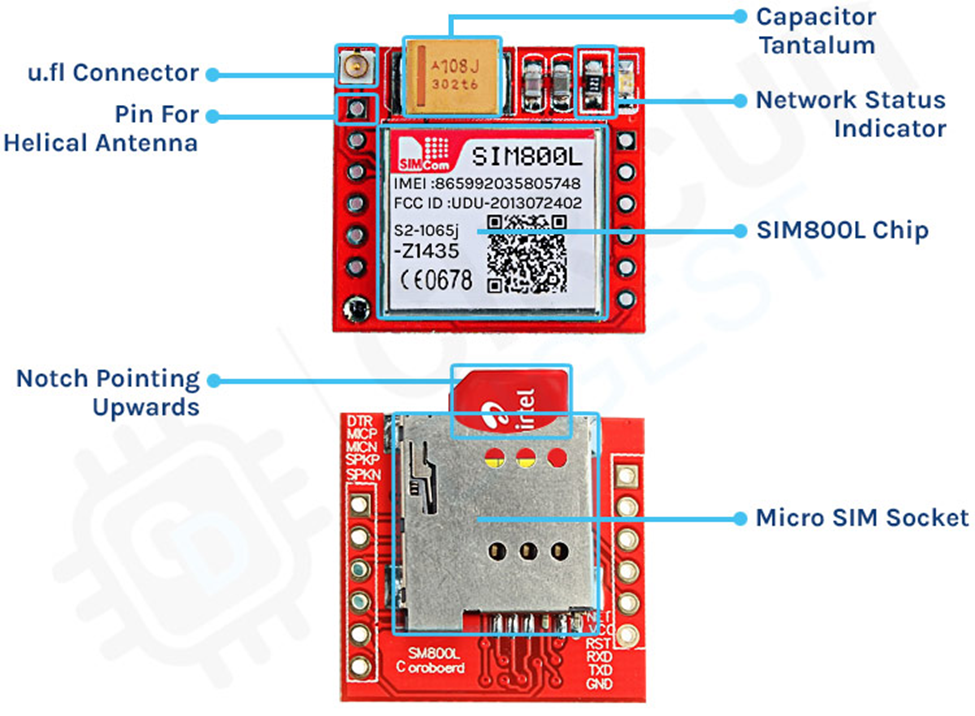
SIM800L GSM/GPRS Module Parts
The SIM800L module is a compact, versatile, and easy-to-use module for GSM and GPRS. The parts marking of the module is shown below.
The code to communicate with the SIM800L GSM/GPRS module is very simple and easy to understand. The code uses the UART2 of the ESP32 microcontroller to communicate with the SIM800 module and the UART0 is used for debugging.
As this code is very simple, we don’t need any external libraries for this code to work. We start our code with our setup function, in the setup function we use the Serial.begin() and Serial2.begin() method to enable UART0 and UART2 of the ESP32 board, then we wait for 3 seconds to give some time to the SIM module to power up, next we call the test_sim800_module() function that is a custom function and we will explain it later. Next, we called the send_SMS() function to send an SMS through the module to test if it’s working or not.
1. void setup() {
2.   Serial.begin(115200);
3.   Serial2.begin(115200);
4.   delay(3000);
5.   test_sim800_module();
6.   send_SMS();
7. }
Next we have our loop() function. In the loop function, we only call the updateSerial() function to test any custom command through the serial monitor window.
1. void loop() {
2. updateSerial();
3. }
Next we have our test_sim800_module() function. This function goes through some AT commands of the sim800L module and the output will tell you if the module is working or not.
AT: AT is the most basic command. Running this and hitting enter returns OK, which means the communication with the serial module is wrong properly.
AT+CSQ: This command checks the signal strength. The first integer value checks the strength in dB. To work with the module the signal strength should be greater than 5. The higher the number, the better the signal strength.
AT+CCID: This command checks the sim card number that is written on the backside of the sim card. After running the command you can verify the number manually. This also can be used to test if the sim card connects to the module.
AT+CREG?: This command is used to check that you’re registered on the network. The second output integer should be 1 or 5. 1 represents that you are in the home network and 5 represents that you are in the roaming network, any other value indicates that you are not registered to a network.
ATI: This command gets the module’s name and number.
AT+COPS?: This command checks that you’re connected to the network, in our case it’s Airtel.
AT+CBC: This command returns the battery percentage if connected with the module. The second number in the output window is the battery percentage.
 1. void test_sim800_module()
 2. {
 3.   Serial2.println("AT");
 4.   updateSerial();
 5.   Serial.println();
 6.   Serial2.println("AT+CSQ");
 7.   updateSerial();
 8.   Serial2.println("AT+CCID");
 9.   updateSerial();
10.   Serial2.println("AT+CREG?");
11.   updateSerial();
12.   Serial2.println("ATI");
13.   updateSerial()
14.   Serial2.println("AT+CBC");
15.   updateSerial();
16. }
Next, we have the updateSerial() function, in this function, we just check the serial function in a callback loop.
 1. void updateSerial()
 2. {
 3.   delay(500);
 4.   while (Serial.available())
 5.   {
 6.     Serial2.write(Serial.read());//Forward what Serial received to Software Serial Port
 7.   }
 8.   while (Serial2.available())
 9.   {
10.     Serial.write(Serial2.read());//Forward what Software Serial received to Serial Port
11.   }
12. }
Next, we have the send_SMS() function. In this function, we configure the SIM800L module in text mode and we call the update serial function so that we could check the output in the serial monitor window. Next, we set the phone number to which we need to send our SMS. Next, we write our message and write 26 with the Serial2.write(26) function, this writes ctrl+C on the serial which is the command for sending the message with serial.
 1. void send_SMS()
 2. {
 3.   Serial2.println("AT+CMGF=1"); // Configuring TEXT mode
 4.   updateSerial();
 5.   Serial2.println("AT+CMGS=\"+919804049270\"");//change ZZ with country code and xxxxxxxxxxx with phone number to sms
 6.   updateSerial();
 7.   Serial2.print("Circuit Digest"); //text content
 8.   updateSerial();
 9.   Serial2.write(26);
10. }
Code for Interfacing SIM800L with ESP32
 1. void setup() {
 2.   Serial.begin(9600);
 3.   Serial2.begin(9600);
 4.   delay(3000);
 5.   test_sim800_module();
 6.   send_SMS();
 7. }
 8. void loop() {
 9.   updateSerial();
10. }
11. void test_sim800_module()
12. {
13.   Serial2.println("AT");
14.   updateSerial();
15.   Serial.println();
16.   Serial2.println("AT+CSQ");
17.   updateSerial();
18.   Serial2.println("AT+CCID");
19.   updateSerial();
20.   Serial2.println("AT+CREG?");
21.   updateSerial();
22.   Serial2.println("ATI");
23.   updateSerial();
24.   Serial2.println("AT+CBC");
25.   updateSerial();
26. }
27. void updateSerial()
28. {
29.   delay(500);
30.   while (Serial.available())
31.   {
32.     Serial2.write(Serial.read());//Forward what Serial received to Software Serial Port
33.   }
34.   while (Serial2.available())
35.   {
36.     Serial.write(Serial2.read());//Forward what Software Serial received to Serial Port
37.   }
38. }
39. void send_SMS()
40. {
41.   Serial2.println("AT+CMGF=1"); // Configuring TEXT mode
42.   updateSerial();
43.   Serial2.println("AT+CMGS=\"+919804049270\"");//change ZZ with country code and xxxxxxxxxxx with phone number to sms
44.   updateSerial();
45.   Serial2.print("Circuit Digest"); //text content
46.   updateSerial();
47. Serial.println();
48.   Serial.println("Message Sent");
49.   Serial2.write(26);
50.  }