
GSM with Connect all
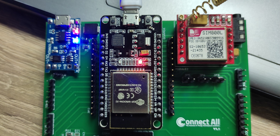
SIM800L GSM/GPRS pinout The SIM800L GSM/GPRS module has 12 pins which are NET, VCC, RST, RXD, TXD, GND, SPK-, SPK+, MIC-, MIC+, DTR, RING. NET is a pin where you can solder the helical antenna that comes with the module. VCC is the Power supply pin of the module, and it needs to be powered anywhere from 3.4V to 4.4 volts. Connecting this module to a 5V supply will most likely destroy it and if you connect it to 3.3V it won’t even run. A lithium battery or a buck converter with 2A current capacity is recommended for this module. RST is the hard reset pin of the sim800L module. If you are having trouble communicating with this, pull the pin low for 100ms. RXD is the RX pin for the module used in serial communication. TXD is the TX pin for this module used in Serial communication. GND is the Ground pin for this module; connect this pin to the Ground pin of the ESP32. RING is the ring indicator pin of the module. This pin generally is active high. It will go low for 120ms to indicate incoming calls and can also be configured to pulse when an SMS is received. DTR this pin can be used to put the module in sleep mode. Pulling the pin high puts the module in sleep mode and disables the serial. Pulling it low will wake the module up. MIC+- These two pins can be used to connect an external microphone to the module. SPK+- these two pins can be used to connect an external speaker to the module. SIM800L GSM/GPRS Module Parts The SIM800L module is a compact, versatile, and easy-to-use module for GSM and GPRS. The parts marking of the module is shown below. The code to communicate with the SIM800L GSM/GPRS module is very simple and easy to understand. The code uses the UART2 of the ESP32 microcontroller to communicate with the SIM800 module and the UART0 is used for debugging. As this code is very simple, we don’t need any external libraries for this code to work. We start our code with our setup function, in the setup function we use the Serial.begin() and Serial2.begin() method to enable UART0 and UART2 of the ESP32 board, then we wait for 3 seconds to give some time to the SIM module to power up, next we call the test_sim800_module() function that is a custom function and we will explain it later. Next, we called the send_SMS() function to send an SMS through the module to test if it’s working or not. Next we have our loop() function. In the loop function, we only call the updateSerial() function to test any custom command through the serial monitor window. Next we have our test_sim800_module() function. This function goes through some AT commands of the sim800L module and the output will tell you if the module is working or not. AT: AT is the most basic command. Running this and hitting enter returns OK, which means the communication with the serial module is wrong properly. AT+CSQ: This command checks the signal strength. The first integer value checks the strength in dB. To work with the module the signal strength should be greater than 5. The higher the number, the better the signal strength. AT+CCID: This command checks the sim card number that is written on the backside of the sim card. After running the command you can verify the number manually. This also can be used to test if the sim card connects to the module. AT+CREG?: This command is used to check that you’re registered on the network. The second output integer should be 1 or 5. 1 represents that you are in the home network and 5 represents that you are in the roaming network, any other value indicates that you are not registered to a network. ATI: This command gets the module’s name and number. AT+COPS?: This command checks that you’re connected to the network, in our case it’s Airtel. AT+CBC: This command returns the battery percentage if connected with the module. The second number in the output window is the battery percentage. Next, we have the updateSerial() function, in this function, we just check the serial function in a callback loop. Next, we have the send_SMS() function. In this function, we configure the SIM800L module in text mode and we call the update serial function so that we could check the output in the serial monitor window. Next, we set the phone number to which we need to send our SMS. Next, we write our message and write 26 with the Serial2.write(26) function, this writes ctrl+C on the serial which is the command for sending the message with serial. Code for Interfacing SIM800L with ESP32
PushButton with Leds Control
To start using Pushbuttons or Touch Pins you can use these GPIOs in your code: SW1/P1 connected with GPIO4 SW2/P2 connected with GPIO2 SW3/P3 connected with GPIO15 SW4/P4 connected with GPIO13 SW5/P5 connected with GPIO12 SW6/P6 connected with GPIO14 SW7/P7 connected with GPIO17 JP9 & JP10: these pins used to connect the Pushbuttons to the ESP32 GPIOs pins, in our case we will connect JP10 between 1 and 2 (COM & GND), and for JP9 connect 2 and 3 (COM&3V3) using bridge connector, and then we can test the behavior of the Pushbuttons by pushing any button we will observe the lighting on of the connected LED this the Pushed button. Blinking LED_0 , and toggle LED_3 using Pushbutton_5 Code :
Getting start
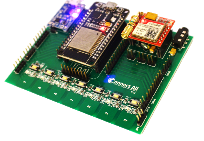
ConnectAll is a breakout platform based on the dev board ESP32 that is meant to breakout meanings of wireless data transfer and connect all of them together with a variety of devices and apps that can be connected over a local WIFI network, or via Bluetooth or even to communicate with GSM and GPRS on one educational platform using minimum power consumption. Specifications & Features This platform is considered a breakout modular development kit which supports plug & play connectivity with multiple operating modes that enables the developer to select between the desired functions. Power Connectivity & Abilities Specifications Pin Configuration ConnectAll V1.1 usage illustration: Mode A: Using the Kit as ESP32 Dev module shield using only JP2 & JP1, and then you can connect whatever you want using the ESP32 pinout configuration. Mode B: Using the Breakout kit with its built-in components such as, LEDs, touch sensors, push button and the GSM module and you can follow the kit instructions to connect the board and start working with it. In case of using the breakout kit as we will follow in the next sessions within the course, let’s go on illustrating the I/O pins of the kit: